| |
| |
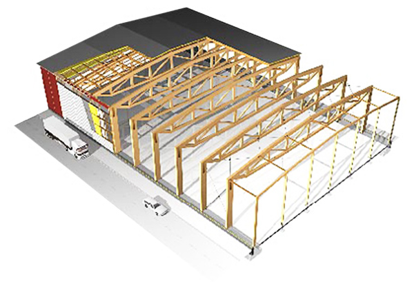
Metal truss is a structure comprising one or more triangular units, constructed with straight members whose ends are connected at joints (nodes). It is a geometrically unchangeable form, which makes the truss rigid enough and reliable for its use as load-bearing element of ceilings and other building structures.
If you take four or more bars and join them randomly by revolute joints, you will get a "variable" unstable structure that will fold due to any impact. If you assemble these rods into conventional triangle, they form a stable structure which is resistant to pressure. This structure will fold only in case when one of the bars is broken or tear off from the others. Therefore, this triangles assembly as a whole behaves as a single object. In this system, external forces and reactions to those forces are considered to act only at the nodes and result in forces in the members which are either tensile or compressive forces.
|
| | |
The use of planar or space frame metal trusses instead of standard beams in construction is considered appropriate when the span without supports exceeds 10 meters. The use of welded steel trusses allows to reduce metal consumption in two or more times in comparison with solid-metal beams, and thus to minimize the weight and cost of the structure. However, the cost reduction will not be proportional, because the welded trusses require much more labor, firstly, for the design (strength analysis), and secondly, for their assembly from a large number of elements. |
| | | |
Company Kiev Crane Factory Ltd. not only manufactures metal trusses, but also makes their design and calculation of load- bearing capacity of welded trusses.
At the first stage of metal truss designing, the choice of are truss shape is made. The geometry of the truss depends on many factors - the purpose of the entire building, the type of roof, type of joint of the truss and columns, the type of loads, which determines how the bending moment of different forces impacts on the truss, as well as other factors.
Trusses calculation methods abound. The so called “method of joint isolation” - one of the easiest (applicable for the calculation of simple plate girders). To calculate the truss strength it is assumed that the loads are applied to joints only and not at intermediate points along the members. Then the truss support reaction is calculated. After this, any node in which there are two bars and applied some forces is analysed. Mentally cutting off the rest of the truss, we receive a node, in which there are several known and two unknown forces and, making the force balance equation on any two axes, are unknown force in the bars are calculated. Then, the next node is cut out, and using already found forces, the acting forces in all bars are computed
Highly qualified engineers in Design Department of Kiev Crane Factory Ltd. will perform the whole range of design work - from initial consultation and concept development - to the elaboration of working documentation in full volume subject to customer needs - quickly, efficiently and cost-effectively!
|
|
| |
Columns are used for load transfer from the upstream structures through the foundations to the ground. Depending on how the load is transferred by the column, columns can be centrally or off-center compressed.
Centrally compressed columns resist the longitudinal force applied to the column axis and causing uniform compression of the cross section.
Off-center compressed columns along with longitudinal axial compression force also takes bending moment.
|
| |
Each column consists of three main parts: - The shaft, which is the main load carrying member of the column;
- The head, supporting the upper structures and distributing the load over the cross section of the shaft;
- The base (shoe), distributing the concentrated load onto the foundation surface and anchoring the column to the foundation.
|
| |
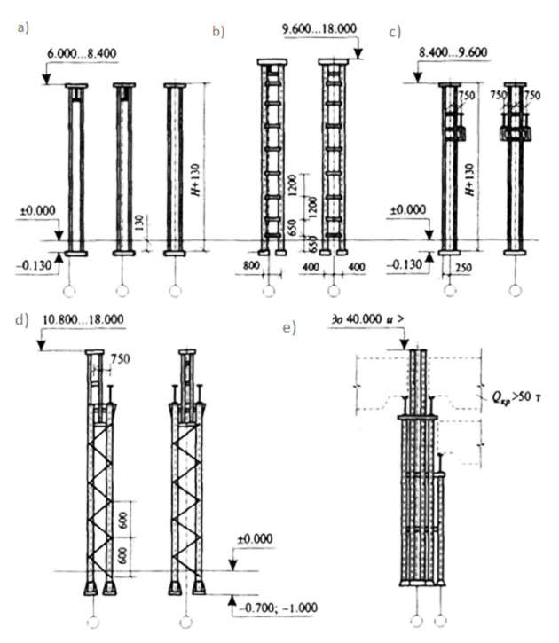
Depending on the building dimensions, availability and type of material lifting and handling equipment and roofing construction, there can be used columns of various types: with solid type shaft or through (trussed) shaft, with uniform or steplike cross-section (Fig. 1).
Columns with solid uniform cross-section (Fig. 1a) are used in buildings without overhead cranes up to 8.4 m height. They are made of I-beams with parallel edges of flanges (wide-flanged beam 35SH1 to 70SH1). Depending on the span, outer rows of columns designed to link "0" (at span 6 m), and "250" (at span 12 m). In buildings without overhead top-running cranes with height 9.6 to 18 m, double-member through (trussed) columns with two plane batten-plate lattice frame are used (Fig. 1,b). Shafts of columns are made of I-beams from № 20 to № 70. The distance between the shafts (the column width) is set made the same for the middle and marginal columns - 800 mm. Columns are designed to bind to the longitudinal alignment axes of 250 mm. Columns members have independent baseplates that are fastened to the foundation with anchor bolts.
For buildings with heights 8.4 to 9.6 m, equipped with overhead top-running cranes up to 20 tons, columns with uniform solid cross-section are designed, and for buildings with cranes up to 50 tons and a height of 10.8 to 18 m – double-member column are used (Fig .1, c, d).
|
| | |
Figure 1. The main types of steel columns:
a – solid uniform cross- section, for buildings without overhead cranes;
b - the same, double-member cross- section;
c - solid cross-section, for buildings equipped with overhead cranes;
d - the same, double-member step like cross-section;
e - the same, separate members step like section.
|
| |
Double-member columns can be used in buildings with spans 18, 24, 30 and 36 m and columns spacing in marginal and middle rows of 12 m. They are designed of step like form, with framework bottom part and solid top part. Crane bearing framework bottom part consists of two shafts: the outer one, as a rule, made of rolled and curved channels, and the crane one – made of wide-flanged I-beams. The lattice of the crane-bearing part is manufactured of two-plane rolled corners.
When using cranes over 50 m lifting capacity in buildings, or for two-tier arrangement and in case of intended facility expansion, separate type columns are used (Fig. 1, e). In such columns crane shaft may be reinforced, for example, crane capacity increasing, and the marginal shaft can be used for workshop expansion.
Column bases have support plates, which are mounted into the foundation at depth around -0,300.
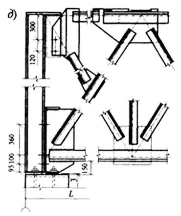
The design of column top (headroom) depends on the connection method with roofing truss. When the hinge connection is used, a support baseplate is welded to the column top, which absorbs the load from the roofing through of the stiffening plate (Fig. 2).
|
| | |
Fig.2. Column top connection with roofing truss structures. |
| |
Steel columns can be used in regions with an estimated outdoor temperature down to -40° C for heated buildings and to -30° C for unheated buildings, constructed in I-IV wind and snow region.
Foundations for steel columns are arranged monolithic, columnar type, without holes (cups). Their are designed the same size as for precast concrete columns. Top edge of foundations are made at a level around -0.7 or -1.0 m, what allows to bury the steel columns base(with cross beams) below the floor level with the further custing with a layer of concrete. For other steel columns, whith no traverses, the foundation is leveled to the mark of 300 mm below the floor level. The column bases are secured to foundations with anchor bolts (Fig. 3, a-e).
|
| | |
Figure 3. Steel columns base and ways of supporting them at the foundations:
a, b - columns base with base plate; c, d - the same, with traverses; e - base of a double-member column; f - the foundation for a steel column; g - steel column and wall support at the basement and the foundation beam; I - column; 2- foundation beam; 3- concrete basement; 4- comcrete. Bases of columns with solid section in buildings without cranes can be placed at the level of the underlying layer of floor construction. This solution is used for supporting of steel framework columns. |
| | |
Experts of Kiev Crane Factory Ltd. provide all kinds of services related to the design, manufacture, delivery and installation of metal columns and trusses, as well as other metal structures of any type and complexity and for wide range of applications, including the manufacture of quickly erected industrial and commercial buildings, mobile towers and other designations.
Highly qualified engineers in Design Department of Kiev Crane Factory Ltd. will perform the whole range of design work - from initial consultation and concept development - to the elaboration of working documentation in full volume subject to customer needs - quickly, efficiently and cost-effectively!
|
|
|
|
|
|